
UART stands for Universal Asynchronous Receiver/Transmitter, however in the context of Hardware Hacking we’re generally looking for an serial interface which will give us text output from the system and possibly allow for command input. The general intention from the manufacturers point of view – is to allow easy debugging, both out of the factor (to check the system is working as intended) and if a device is returned as broken.
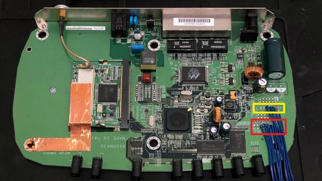
As with JTAG, sometimes it’s conveniently highlighted on a target board for you, as with this example. The below photograph showing an exposed UART in yellow (and incidentally JTAG in red). Here it’s neatly placed to one side of the board to allow for easy access. That’s not necessarily the case, but either way you can find possible UART access with a JTAGulator, as I’ll show.
Discovering UART with the JTAGulator and connecting to it with UART PassThrough and a USB-to-UART!
Introduction
UART stands for Universal Asynchronous Receiver/Transmitter, however in the context of Hardware Hacking we’re generally looking for an serial interface which will give us text output from the system and possibly allow for command input. The general intention from the manufacturers point of view – is to allow easy debugging, both out of the factor (to check the system is working as intended) and if a device is returned as broken.
As with JTAG, sometimes it’s conveniently highlighted on a target board for you, as with this example. The below photograph showing an exposed UART in yellow (and incidentally JTAG in red). Here it’s neatly placed to one side of the board to allow for easy access. That’s not necessarily the case, but either way you can find possible UART access with a JTAGulator, as I’ll show.
An alternative (and cheaper) approach would be to use an Arduino loaded with UARTFuzz.
Finding UART with the JTAGulator
As with my JTAG guide, you will first need to discover a suitable ground pin for connecting the JTAGulator. This is so both devices have a shared reference. Ground points are generally easy to find, as both the power connection and metal parts of the casing tend to be grounded. However if you’re using test-clips like I am, it’s generally better to find a ground (sometimes labelled GRD) pin so that your clip doesn’t pop off during testing.
You can find a ground pin by setting a multi-meter to continuity mode, and placing a probe on a known ground point (such as the metal case, in this example) and a potential ground pin. In the multi-meter shows continuity (the display changes from 1 to something like 0.01) you have a ground pin.
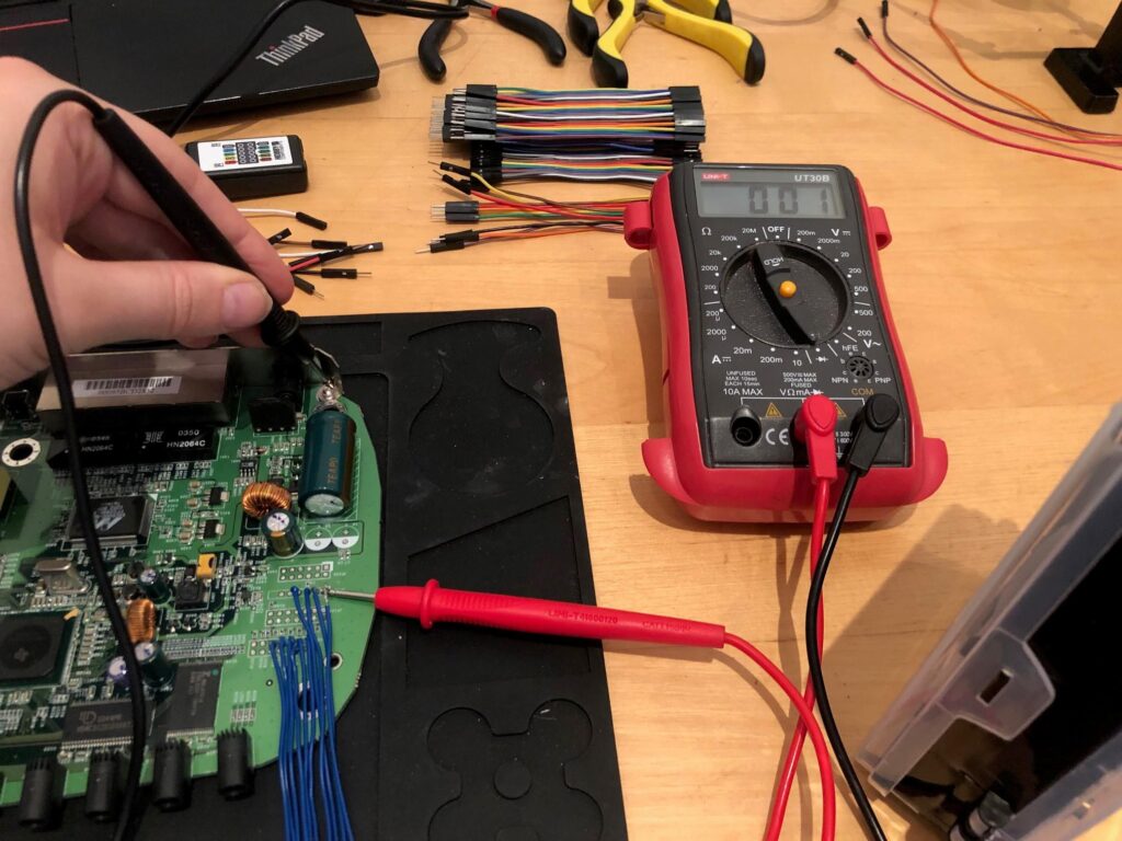
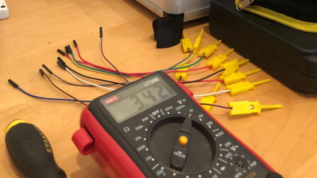
Next we’ll need the target voltage for the system, a datasheet would give you that, but an alternative way would be to test the interface looking for the power rail. Here I’ve placed my multi-meter into voltage mode and am testing each pin in turn, looking for pin that gives a static reading. Like this:
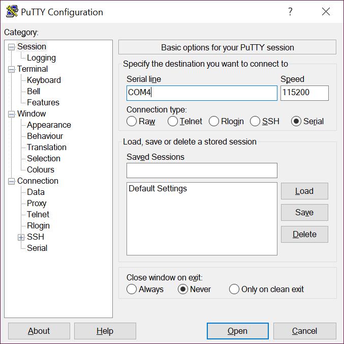
Now I can connect to the JTAGulator, by connecting it to my laptop and using a terminal emulator to communicate with it. On Linux I tend to use screen and on Windows I use putty. Here is my putty configuration. I have used COM4 because on my system that’s where my JTAGulator is, but if you’re in doubt the Device Manager will tell you which one to use. On Linux this would generally be /dev/ttyUSB0. The speed should be 115200.
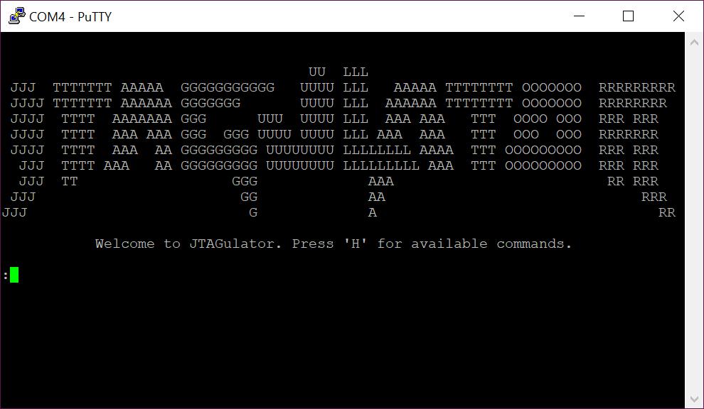
When you’re connected and the JTAGulator starts up, it’ll give you some neat ascii art – if you miss it by having the JTAGulator powered on for a while before you connect Putty to it then you’ll miss it, but hit the reset button on the JTAGulator to see it.
At this point, you can press ‘H’ followed by enter to view the help – or you can jump straight in and set the target voltage with ‘V’ and then typing ‘3.3’ in this case. If you forget this step, when you try to move on the JTAGulator will remind you.
Now we can search for UART interfaces with ‘U’. Then the JTAGulator will ask you what input it should use to find the interface – the default is a carriage return.
However, if you run this test whilst the device is still booting you may get some unintended, but actually quite useful output. For example, if I power up my target board just moments before I perform the scan I get:
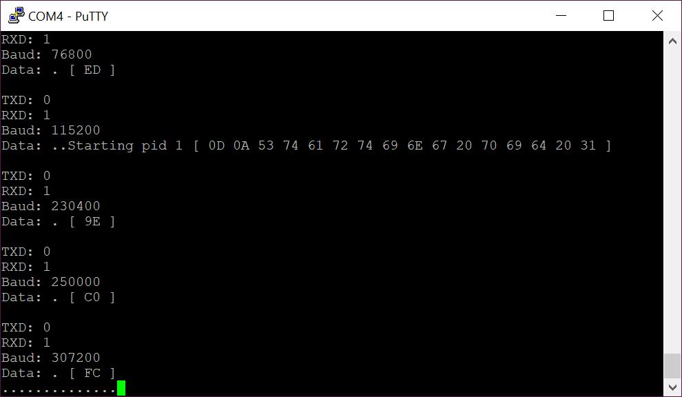
Now to explain the above I should add what the JTAGulator is doing; it’s working through each permutation of pin-out and Baud rate. So you can see here it’s showing what it tested for pins and speed, followed by what it’s input (the default being a carriage return) returned. In the above screenshot we can see that it has accurately identified a UART interface with pin out TX: 0, RX: 1, Baud 115200. You can determine this as the input (carriage return) was echoed back (shown in that lines hex output as 0A 0D).
However you can also see that as the device was still booting, the JTAgulator has cause some of the bootup message (“Starting PID” in this case). Which makes it nice and obvious which pin out worked. We got an obvious readout showing that RX is working and because it echoed our 0A 0D that shows that TX is likely working too).
If I had waited a little longer (e.g. the system wasn’t in the process of outputting boot messages). I would have just had the 0A 0D returned, which is easy to miss. You don’t have to use the default string though, an alternative which works nicely on this device is 0x6c730A0D (That’s the “ls” Linux command followed by a line-fee-carriage-return). Which results in this:
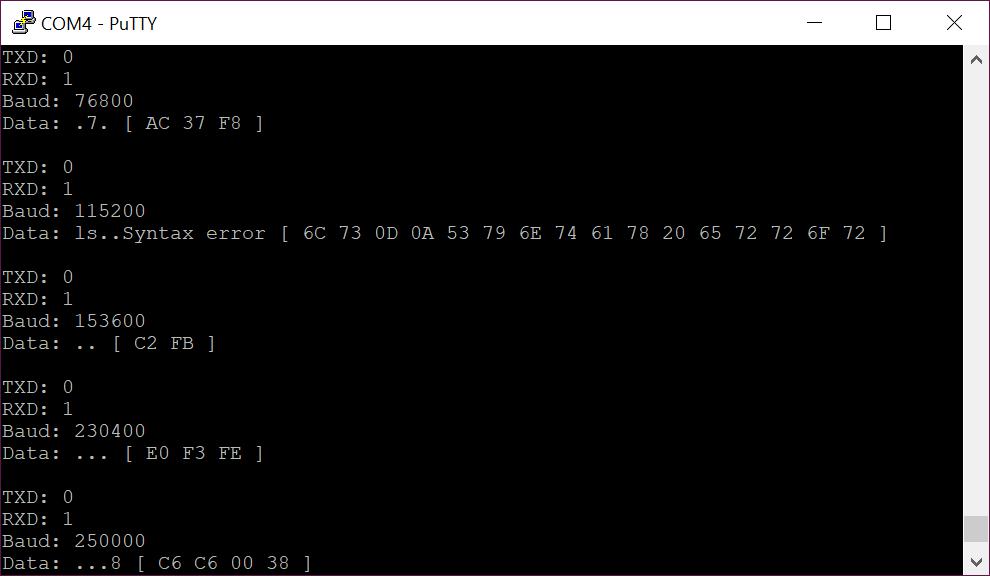
Here you can see our input (a Linux command) caused a command syntax error, nicely confirming that the pin-out TX:0, RX: 1, Baud: 115200 is working.
Your mileage here will vary, how the serial interface reacts to your input will greatly rely on what the system is running on that interface. Supplying the default carriage return and receiving the following back is a strong indicator or a working UART:
Data: .. [ 0A 0D ]Now that we’ve found a working UART pinout we can connect to it with either the JTAGulator’s UART PassThrough or another device. Passthrough is useful for having just a quick test of the interface to see what it’s running. For longer or more involved tests I usually swap to something like a USB-to-UART, to free up the JTAGulator for colleagues and other tasks.
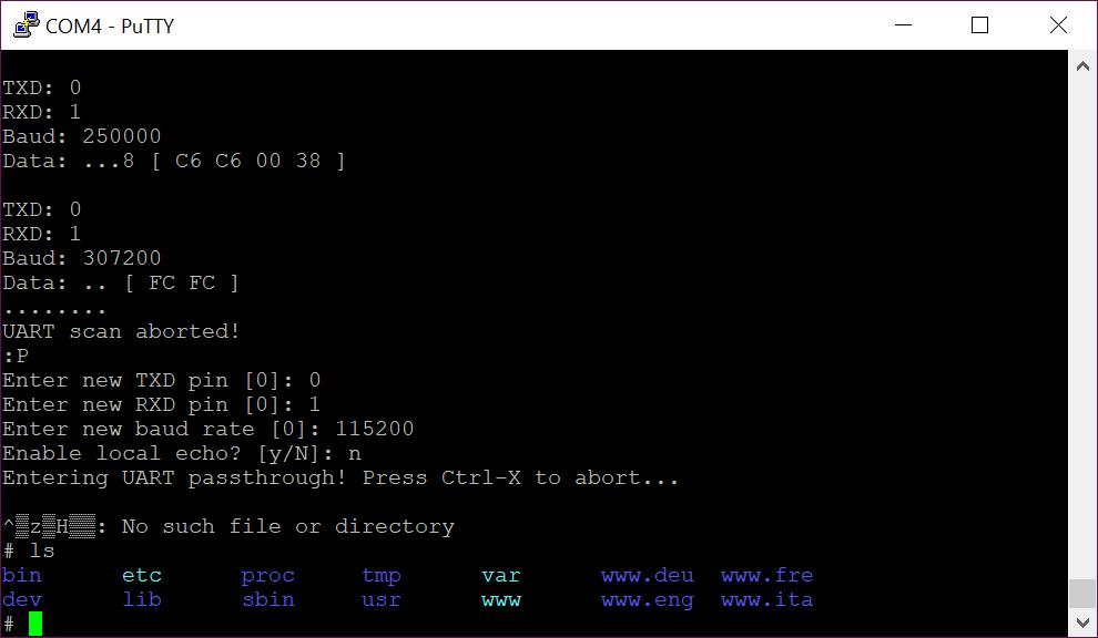
In this case, we’ve been dropped straight into a root shell on the device and can execute a small number of simple *nix commands. Although we have a root shell we’re not done with the hardware test! Compromising a single device is one thing, but if we can find access keys or network vulnerabilities we could use this access to compromise all similar devices we come across.
If you’re like me and you prefer to free up the JTAGulator at this point, but want to keep playing with your fancy root shell – you can use one of these:
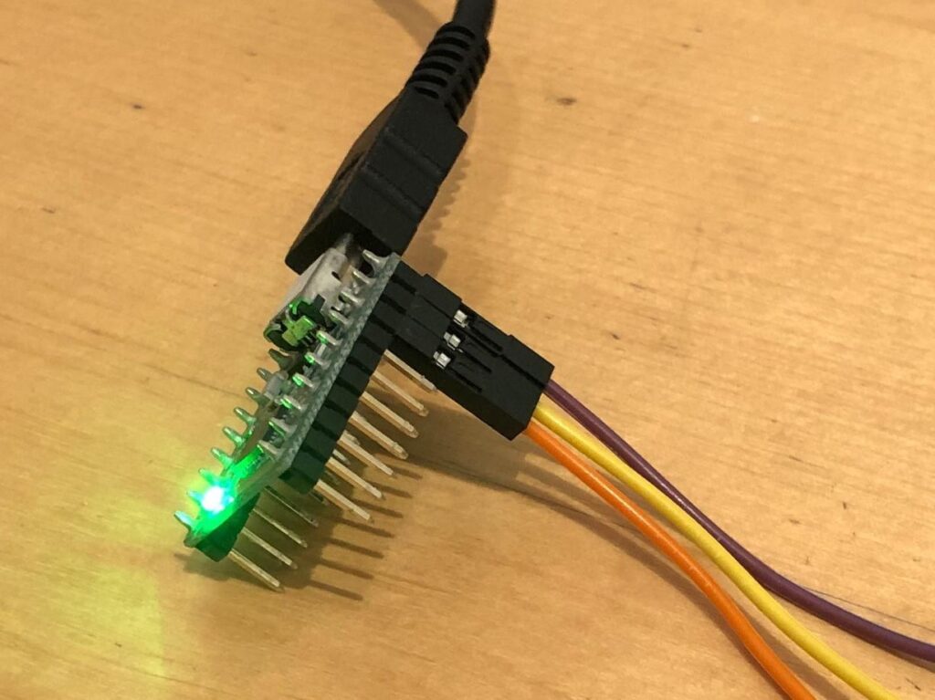
This device is a CP2102N “USB-to-UART”, which has the pinout:
Purple - GRD
Yellow - TX
Orange - RX
However remember that you’ll need to connect the TX of the CP2102N to the RX of the target board, and the RX into the TX. So that they can receive our transmission and we can receive theirs. That might sound obvious but next time you’re hacking and are a little short on coffee you’ll find it’s an easy mistake to make!
The only noticeable difference for me once I move from the JTAGulator to the CP2102N is that my COM port changes, so remember to change it in Putty as you connect to whatever your chip uses and check Device Manager (or dmesg) if you’re unsure what number to use.
You’ve successfully found a UART interface, if you’re having an easy day you’ll now have a root shell and if not then maybe you’ll just get a little debug output, but either way – have fun!
That’s it!
A Quick Malware Teardown
A follower sent me a suspicious looking file recently to get my opinion on its behavior and to see if I could pull out a little detail on how it’s working. “Suspicious looking” because at the time, it was getting a zero score on VirusTotal but it appeared to be [...]| Play | Cover | Release Label |
Track Title Track Authors |
|---|